By Lawrence Tattersall
Thursday, the 6th February 2020, is now a special day in the history of Beeleigh Mill – after 145 years of quiescence our Beam Engine was galloping away! A most exciting vision for the volunteers of BMRG.
This day was the culmination of ten years of dedicated work: stripping the Engine to its components, recording those components, cleaning them (having to replace a few), re-assembling them and performing some very accurate positional adjustments to achieve perfect piston alignments.
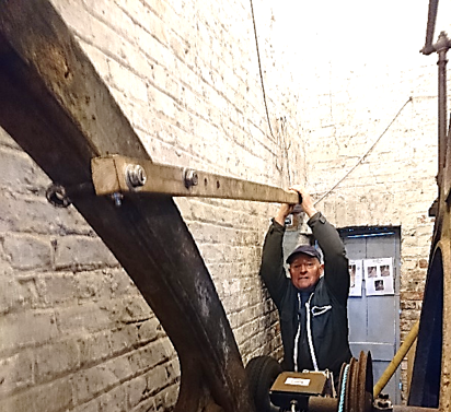
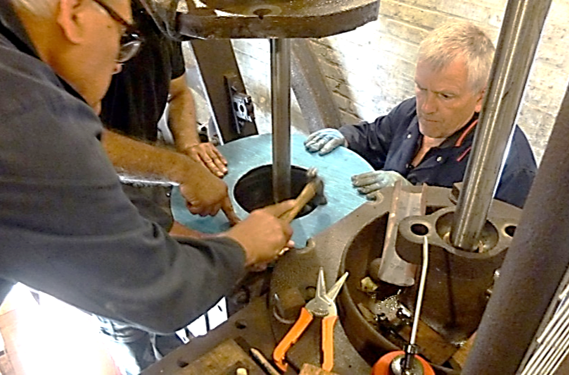
Turning the engine over by hand (Fig. 1) was the first attempt at beam oscillation. It was progressively successful and very hard work but it gave us the opportunity to make further adjustments and to test our gaskets and gland packings as we added these stage by stage (Fig. 2).
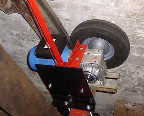
The next big step was to design, build and install an electric motor drive using a tyre pressed against the flywheel (Fig. 3). A major problem with the initial mechanism was the huge momentum of the flywheel (which is what it’s designed to have!) which destroyed the ratchet guide of the cam-clutch bearing. However, the failure did not occur until many of our 2019 open days’ visitors witnessed the slow turning of the Engine.
The Engine Team Leader, David Morgan, then led the planning and design of our next challenging stage – that of running the Engine on compressed air. A very detailed and complex Method Statement and a Risk Assessment were produced and presented to our ECC Millwright, James Owden, for approval – and we received the go-ahead!
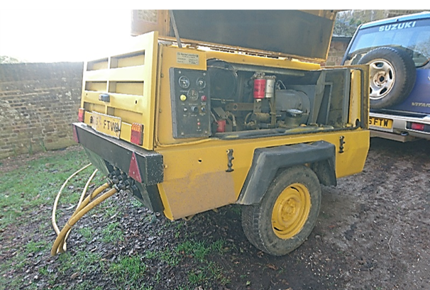
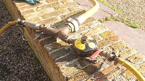
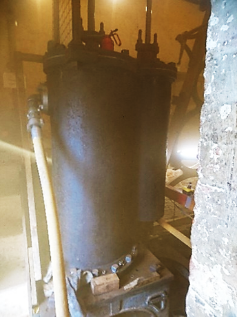
The problem with compressed air, compared with steam (our eventual target medium), is that it takes very large volumes to do any significant amount of work. But thanks to Team Member Les Peck, who very generously lent us an industrial sized diesel driven compressor (Fig. 4) together with the necessary pressure hoses, couplings, oiler, water ejector and safety coupling over-straps, (Fig. 5) we were in business.
It was critical that we did not introduce abrasive particles into the cylinders so we first ‘blew out’ each of the hoses followed by the steam jacket surrounding the cylinder block. That was our first surprise: the sheer volume of dust emerging from the removed jacket drain plug was astonishing. The photo. (Fig.6) does not do the choking fog situation justice.
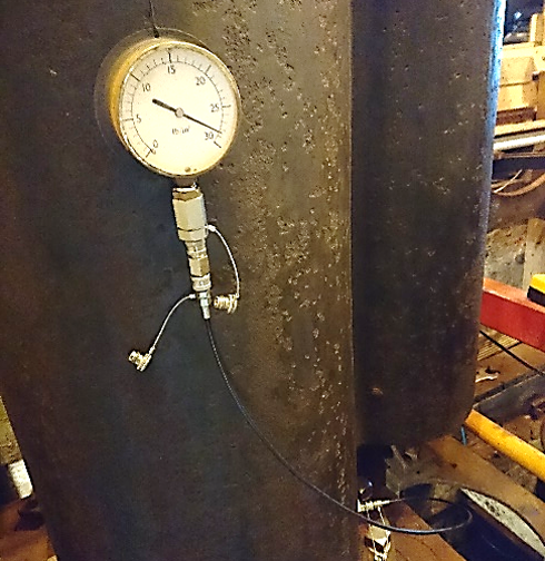
We inserted a calibrated pressure gauge into the drain plug socket (Fig. 7) to be able to continually monitor our operating pressure.
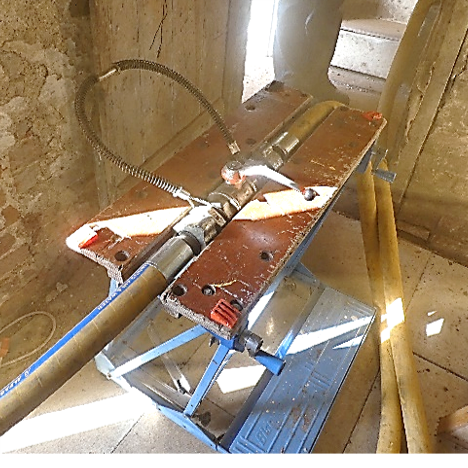
We anchored our master control valve into the B & D Workmate (Fig. 8) to have one member always on station for rapid shut off; we positioned two other look-outs in the yard and at the compressor so that we always had a line-of-sight command route.
The best chance of the air having enough pressure and volume to actually turn the Engine was to start with only the high pressure (smaller diameter) piston and to position the pistons halfway up the cylinders. Thus, we were ready to roll!
COMPRESSED AIR ON !
It was the most exciting scene I have ever seen since we started this project – the Engine smoothly turning at 28 rpm with the hiss of escaping air into the currently non-installed condenser under the block. “Just like a steam engine pulling out of the station” someone observed.